Solved Build the motorcontrol circuit below that includes Circuit Diagram This example covers a hypothetical and uses the principles of high-power design to improve a high-power motor driver application. Note, this example serves to show that how the process is utilized and rest of the application note explains the theory that eventually results in the process used. Consider the following example:
A switching regulator has higher efficiency and less power loss, and PWM is widely used in speed controller design for DC motors. Motor Power. Motor power relies on the current supplied by the power source. Thus, a low-power BDC motor needs a low current controller and vice versa. A high current DC motor controller typically uses a switching

System Design Considerations for High Circuit Diagram
The goal of this project is to design a high-power motor driver that can: 1. Drive a DC motor with a high current rating (up to 40A). 2. Allow control over motor speed and direction. 3. Be used in various high-power applications such as robotics, electric vehicles, or heavy machinery. 4.
Motor Structure + Design. Motors have a standard set of parameters that determine their performance, we design to these parameters, but they also have many considerations associated with them. Here are some. General selection of poles and slots in motor design. Power + Transmission Design MIT 2.75 - look @ the middle section about motors after researching commercially available motor driver boards and finding that most were either kinda wimpy(see included comparison photo) or rather expensive i decided to design a simple Arduino based solution Design Brief . 24v minimum. bi-directional motor control. PWM control. scalable high current capable( 100AMP) minimal components. 5v
Power Motor Driver Using the FGH40N60SFD MOSFET Circuit Diagram
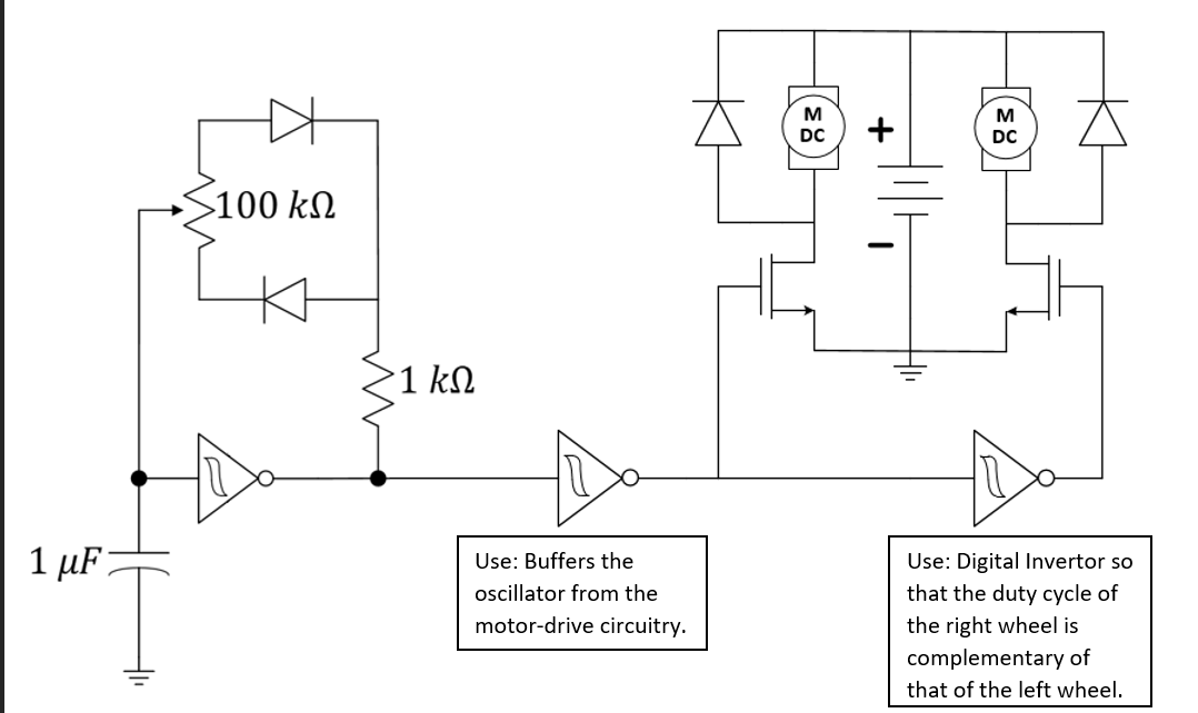
Design#2: PWM DC Motor Control with IC 555. The design of a simple motor speed controller using PWM may be understood as follows: Initially when the circuit is powered, the trigger pin is in a logic low position since the capacitor C1 is not charged. The above conditions initiates the oscillation cycle, making the output change to a logic high. In this guide, we will explore different types of motor control circuits, including their wiring diagrams and key advantages and disadvantages. Types of Motor Control Circuits. Direct Online (DOL) Starter; ü Simple and cost-effective. ü High starting current, leading to voltage drops. ü Suitable for smaller motors
